STM32 & OpenCM3 Part 2: SPI and DMA
Thu, Sep 13, 2018 Companion code for this post available on GithubIn the
previous section,
we covered alternate functions, and configured a log console over UART.
This time, we’ll take a look at the SPI peripherals available on the STM32F0,
use them to quickly shift out data to some shift registers, and then demonstrate
how to then offload that transfer from the main CPU using DMA. Since we have
some other ICs involved here, instead of the simple breakout from before I will
be using this MIDI relay board as a demonstration piece:
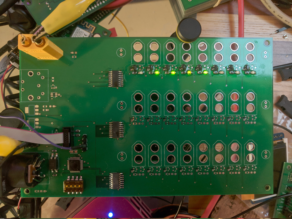
MIDI solenoid control board (a work in progress).
The ICs of interest here are the row of shift registers down the middle,
each of which is responsible for driving the eight FETs by each of the solenoid
connection points. For this example I have only populated the first row of 8,
but this will be enough to demonstrate. Our STM32F070 IC, SWD header and uart
breakout are visible in the bottom left corner of the board. Shift registers,
for those that aren’t familiar, allow one to take serial data and convert it to
a parallel output. These ICs are
74HC595
models, which are 8-bit shift registers with separate shift and storage
registers. But how do we get the data in there? From the datasheet, we can find
this table defining the behaviour as we manipulate the control inputs:
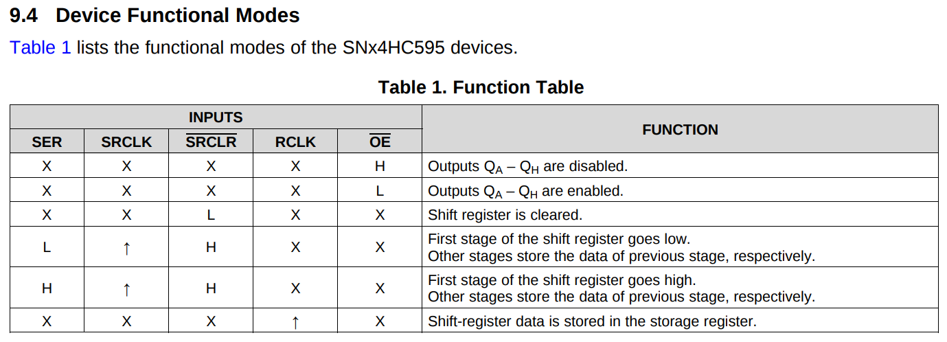
Functional description of the 595 shift register
So in order to shift data, we cycle SRCLK and on each rising edge the data
on SER will be shifted in to the shift register, and all data presently in
the shift register will be shifted over one. Once we have repeated this to load
as much data as we might want to, we can then clock the RCLK line from low to
high to shift the data in the shift register to the storage register, making it
visible on the outputs.
Now, to drive this we could write a method that carefully takes each byte we
want to send and iterates along each bit inside it, manually toggling the SER
and SRCLK lines to shift data in. But this would be tedious, slow, and
duplicating a built-in peripheral that does exactly the same thing: SPI!
Serial Peripheral Interface
The SPI protocol is a simple communication interface usually consisting of 4 signals:
- MOSI (Master Out Slave In)
- MISO (Master In Slave Out)
- SCK (Serial ClocK)
- SS (Slave Select)
Unlike UART, this protocol has a clock signal - as a result, SPI buses can be operated at far higher speeds since both sides can know precisely when to latch each bit. Like UART, it is a duplex - the MOSI and MISO lines are each unidirectional, and can both transmit data during the same clock pulse. However, SPI also allows for multiple slaves (and, in more complex setups, multiple masters) on the same MISO and MOSI lines. In order to prevent slaves from reading / writing data not intended for them, the Slave Select signal is used to identify which chip is being addressed. Notably, the SS signal is active low - this means that we can use our SPI MOSI, SCK and SS lines to map perfectly to the SER, SRCLK and RCLK lines of our shift registers. Using this information, we can codify it in our schematic like so:
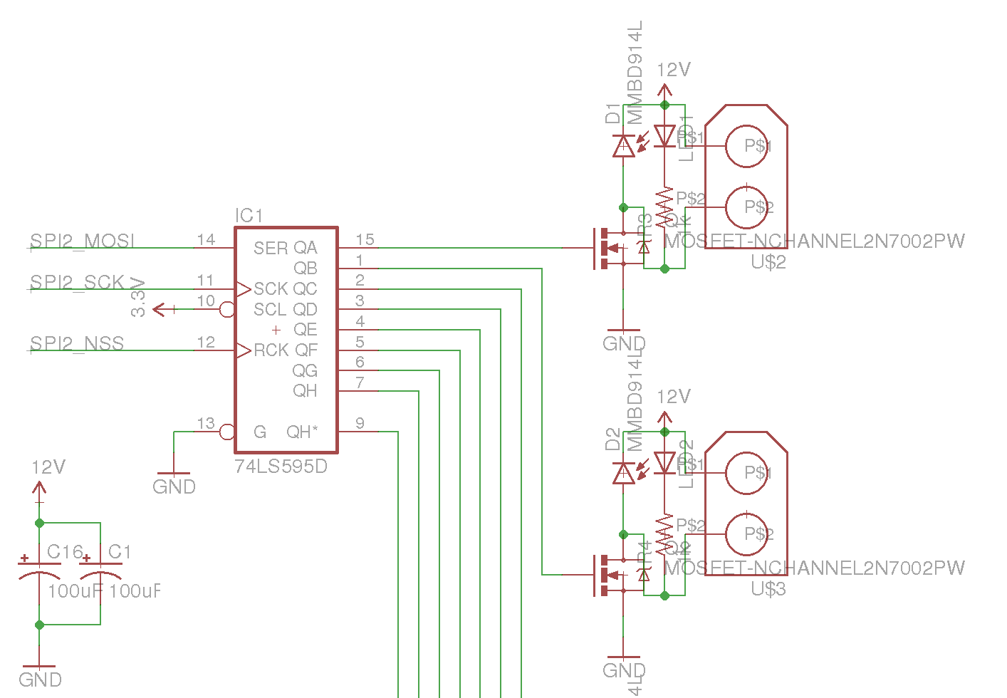
SPI connections for driving shift register. Additional 595s are fed the same SCK and NSS signals, but chained QH* -> SER.
So now that we have our SPI pins mapped to our shift register (in this case, we are using PB12-PB15 and the SPI2 peripheral), we can start start work on initializing our SPI peripheral in preparation for sending data through it.
void spi_setup() {
    // Enable clock for SPI2 peripheral
    rcc_periph_clock_enable(RCC_SPI2);

    // Configure GPIOB, AF0: SCK = PB13, MISO = PB14, MOSI = PB15
    gpio_mode_setup(GPIOB, GPIO_MODE_AF, GPIO_PUPD_NONE, GPIO13 | GPIO14 | GPIO15);
    gpio_set_af(GPIOB, GPIO_AF0, GPIO13 | GPIO14 | GPIO15);

    // We will be manually controlling the SS pin here, so set it as a normal output
    gpio_mode_setup(GPIOB, GPIO_MODE_OUTPUT, GPIO_PUPD_NONE, GPIO12);

    // SS is active low, so pull it high for now
    gpio_set(GPIOB, GPIO12);

    // Reset our peripheral
    spi_reset(SPI2);

    // Set main SPI settings:
    // - The datasheet for the 74HC595 specifies a max frequency at 4.5V of
    //   25MHz, but since we're running at 3.3V we'll instead use a 12MHz
    //   clock, or 1/4 of our main clock speed.
    // - Set the clock polarity to be zero at idle
    // - Set the clock phase to trigger on the rising edge, as per datasheet
    // - Send the most significant bit (MSB) first
    spi_init_master(
        SPI2,
        SPI_CR1_BAUDRATE_FPCLK_DIV_4,
        SPI_CR1_CPOL_CLK_TO_0_WHEN_IDLE,
        SPI_CR1_CPHA_CLK_TRANSITION_1,
        SPI_CR1_MSBFIRST
    );

    // Since we are manually managing the SS line, we need to move it to
    // software control here.
    spi_enable_software_slave_management(SPI2);

    // We also need to set the value of NSS high, so that our SPI peripheral
    // doesn't think it is itself in slave mode.
    spi_set_nss_high(SPI2);

    // The terminology around directionality can be a little confusing here -
    // unidirectional mode means that this is the only chip initiating
    // transfers, not that it will ignore any incoming data on the MISO pin.
    // Enabling duplex is required to read data back however.
    spi_set_unidirectional_mode(SPI2);

    // We're using 8 bit, not 16 bit, transfers
    spi_set_data_size(SPI2, SPI_CR2_DS_8BIT);

    // Enable the peripheral
    spi_enable(SPI2);
}
Our SPI peripheral should now be ready to transmit data. In order to make things easier for us, let’s create a simple helper method that will transmit a given amount of data over the SPI bus:
void spi_transfer(uint8_t tx_count, uint8_t *tx_data) {
    // Pull CS low to select target. In our case, this just pulls the register
    // clock low so that we can lock in the new data at the end of the
    // transfer.
    gpio_clear(GPIOB, GPIO12);

    // For each byte of data we want to transmit
    for (uint8_t i = 0; i < tx_count; i++) {
        // Wait for the peripheral to become ready to transmit (transmit buffer
        // empty flag set)
        while (!(SPI_SR(SPI2) & SPI_SR_TXE));

        // Place the next data in the data register for transmission
        SPI_DR8(SPI2) = tx_data[i];
    }

    // Putting data into the SPI_DR register doesn't block - it will start
    // sending the data asynchronously with the main CPU. To make sure that the
    // data is finished sending before we pull the register clock high again,
    // we wait here until the busy flag is cleared on the SPI peripheral.
    while (SPI_SR(SPI2) & SPI_SR_BSY);

    // Bring the SS pin high again to latch the new data
    gpio_set(GPIOB, GPIO12);
}
So now we should be able to easily clock out data to our shift registers over SPI. To test this, let’s update our main loop from last time:
int main() {
    // Clock, UART, etc setup
    // [...]

    // Initialize our SPI peripheral
    spi_setup();

    // Make a very simple count up display using our 8 LEDs
    uint8_t i = 0;
    while (1) {
        i++;
        spi_transfer(1, &i);
        delay(1000);
    }
}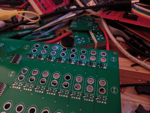
Shift register output
Perfect, we can see that we are slowly counting up. Now, this is obviously a fairly small application of SPI - we only have 8 bits to transfer here (24 for a fully populated board); it will take a truly infinitessimal time to push this data. But if you have a lot of data to move, for example bitmap data you need to push to a screen, the amount of time it takes to move that data from memory to the SPI bus might start to become a problem - while you’re looping over all the data to send and moving it piece by piece to the SPI data register, you’re losing time to process other events or start drawing the next frame. Wouldn’t it be great if something so simple as moving data from memory to a peripheral could be offloaded somehow?
Direct Memory Access
DMA controllers allow us to offload certain types of data shuffling from the main processor, freeing it to get on with business. In the STM32F0 series, the controller can be used to move data between two peripherals, from a peripheral into memory, or from memory to a peripheral. For this example, we’re going to use it to copy data from memory to our SPI peripheral, so that it can be sent our to our shift registers. Each DMA controller has multiple channels, and those channels are all bound to specific peripheral functions. If we take a look at the STM32F0 series datasheet, we can find a table showing us which channels map to which peripherals.
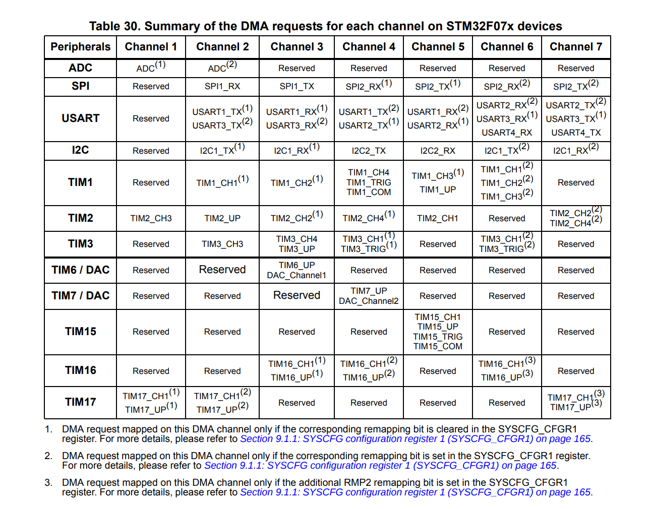
DMA channel mapping for the STM32F070 MCU
Based on this, we can see that in order to transmit data on SPI2, we need to use DMA channel 5. So let’s start configuring our DMA controller:
void dma_init() {
    // Enable DMA clock
    rcc_periph_clock_enable(RCC_DMA1);
    // In order to use SPI2_TX, we need DMA 1 Channel 5
    dma_channel_reset(DMA1, DMA_CHANNEL5);
    // SPI2 data register as output
    dma_set_peripheral_address(DMA1, DMA_CHANNEL5, (uint32_t)&SPI2_DR);
    // We will be using system memory as the source data
    dma_set_read_from_memory(DMA1, DMA_CHANNEL5);
    // Memory increment mode needs to be turned on, so that if we're sending
    // multiple bytes the DMA controller actually sends a series of bytes,
    // instead of the same byte multiple times.
    dma_enable_memory_increment_mode(DMA1, DMA_CHANNEL5);
    // Contrarily, the peripheral does not need to be incremented - the SPI
    // data register doesn't move around as we write to it.
    dma_disable_peripheral_increment_mode(DMA1, DMA_CHANNEL5);
    // We want to use 8 bit transfers
    dma_set_peripheral_size(DMA1, DMA_CHANNEL5, DMA_CCR_PSIZE_8BIT);
    dma_set_memory_size(DMA1, DMA_CHANNEL5, DMA_CCR_MSIZE_8BIT);
    // We don't have any other DMA transfers going, but if we did we can use
    // priorities to try to ensure time-critical transfers are not interrupted
    // by others. In this case, it is alone.
    dma_set_priority(DMA1, DMA_CHANNEL5, DMA_CCR_PL_LOW);
    // Since we need to pull the register clock high after the transfer is
    // complete, enable transfer complete interrupts.
    dma_enable_transfer_complete_interrupt(DMA1, DMA_CHANNEL5);
    // We also need to enable the relevant interrupt in the interrupt
    // controller, and assign it a priority.
    nvic_set_priority(NVIC_DMA1_CHANNEL4_5_IRQ, 0);
    nvic_enable_irq(NVIC_DMA1_CHANNEL4_5_IRQ);
}
So now, our DMA controller is all set up to push data from memory to SPI2’s transmit buffer. But note that in our setup we didn’t specify our source memory location or how much data we’re sending - let’s add a method for that now
void dma_start(void *data, size_t data_size) {
    // Note - manipulating the memory address/size of the DMA controller cannot
    // be done while the channel is enabled. Ensure any previous transfer has
    // completed and the channel is disabled before you start another transfer.
    // Tell the DMA controller to start reading memory data from this address
    dma_set_memory_address(DMA1, DMA_CHANNEL5, (uint32_t)data);
    // Configure the number of bytes to transfer
    dma_set_number_of_data(DMA1, DMA_CHANNEL5, data_size);
    // Enable the DMA channel.
    dma_enable_channel(DMA1, DMA_CHANNEL5);

    // Since we're manually controlling our register clock, move it low now
    gpio_clear(GPIOB, GPIO12);

    // Finally, enable SPI DMA transmit. This call is what actually starts the
    // DMA transfer.
    spi_enable_tx_dma(SPI2);
}
But this is only half the process - we also need to handle the termination
condition of the DMA transfer, so that we can move our register clock high
again to latch the data. So for this, we need to implement an interrupt handler
for our DMA channel. DMA channels 4 and 5 use the same ISR -
dma1_channel4_5_isr - so let’s
implement that now.
void dma1_channel4_5_isr() {
    // Check that we got triggered because the transfer is complete, by
    // checking the Transfer Complete Interrupt Flag
    if (dma_get_interrupt_flag(DMA1, DMA_CHANNEL5, DMA_TCIF)) {
        // If that is why we're here, clear the flag for next time
        dma_clear_interrupt_flags(DMA1, DMA_CHANNEL5, DMA_TCIF);

        // Like the non-dma version, we don't want to latch the register clock
        // until the transfer is actually complete, so wait til the busy flag
        // is clear
        while (SPI_SR(SPI2) & SPI_SR_BSY);

        // Turn our DMA channel back off, in preparation of the next transfer
        spi_disable_tx_dma(SPI2);
        dma_disable_channel(DMA1, DMA_CHANNEL5);

        // Bring the register clock high to latch the transferred data
        gpio_set(GPIOB, GPIO12);
    }
}
To tie it all together and demonstrate that the DMA transfer is separate from normal CPU operations, let’s start a DMA transfer and then immediately write some text over the USART.
int main() {
    // Setup clock, serial, spi, etc
    // [...]

    // Initialize the DMA controller
    dma_init();

    // Allocate a nice big slab of data
    uint8_t data[1024];
    for (int i = 0; i < 1024; i++) {
        data[i] = i;
    }

    // Begin a DMA transfer using that data
    dma_start(data, 1024);

    // Immediately start printing some text to our console
    printf("Concurrent DMA and USART!\n");

    while (true) {
        // Nothing
    }

    return 0;
}
If we now tap the UART and SPI lines on the board with a logic analyzer, we can observe that we are indeed sending both SPI and UART data concurrently:
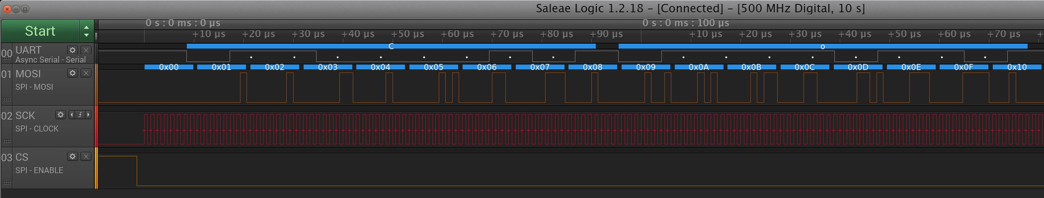
Trace of our SPI bus and UART TX
Success! We can see that while the main thread of execution has moved on to sending data over the USART, the DMA controller has begun sending out kilobyte of data in the background. While DMA is still limited by sharing the same memory and peripheral bus as the processor, and so both must still negotiate if there are bus conflicts, it is a powerful tool for offloading simpler peripheral operations in this way. You can even do more complex DMA operations, such as pushing double-buffering video data bv taking advantage of circular DMA and the “transfer half complete” interrupt.
As per usual, the code for this post is available on Github.
The next post in this series, on CANBus, can be found here