DEFCON 29 Hardware Hacking Village CTF
Sun, Aug 8, 2021This post contains writeups and some code samples for solving each of the puzzles from the DC29 HHV Challenge roughly organized by complexity. Many thanks to the HHV members that ran the CTF (rehr, wintermute, diogt and any others)!
Plenty of spoilers follow!
Welcome
Backup Logs
For part a, we need to take the long view. Shrinking the interface size on Logic makes this a bit easier:
The Big Picture
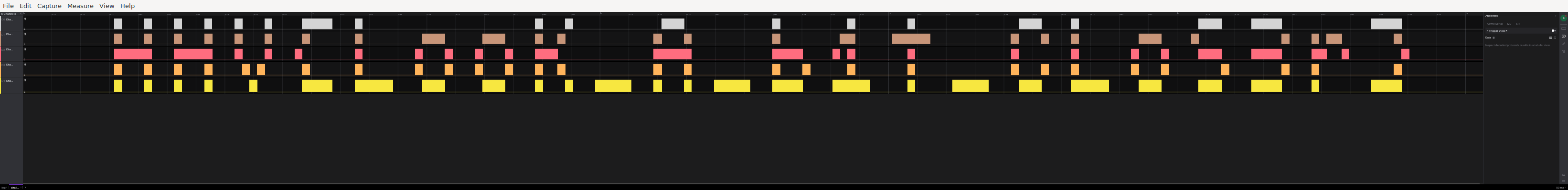
For part b, careful examination of the clock signals (or blindly adding uart decoders to every signal) reveals that one of our channels actually transmits UART data for part of the trace.
Secret board
The filenames in the zip are all .gbr, or Gerber files for PCB fabrication data.
Opening them in a
viewer (e.g. gerbview or gerbv) reveals a nice little badge
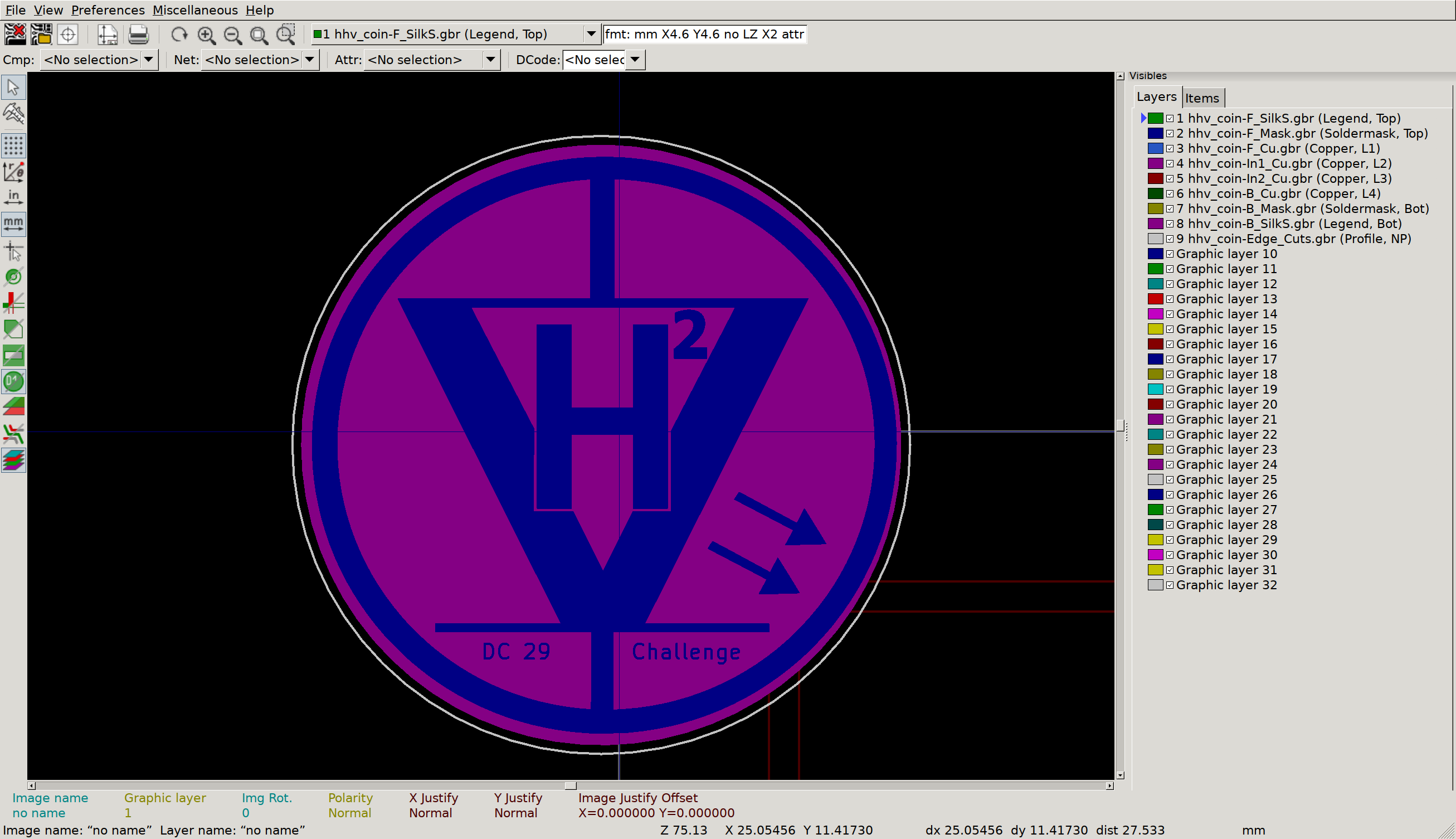
What a nice badge
But what’s this, on the inner copper layers?
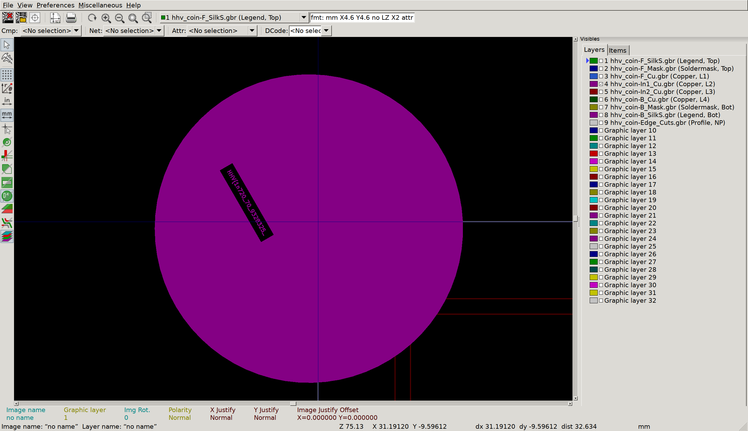
Inner Copper 1
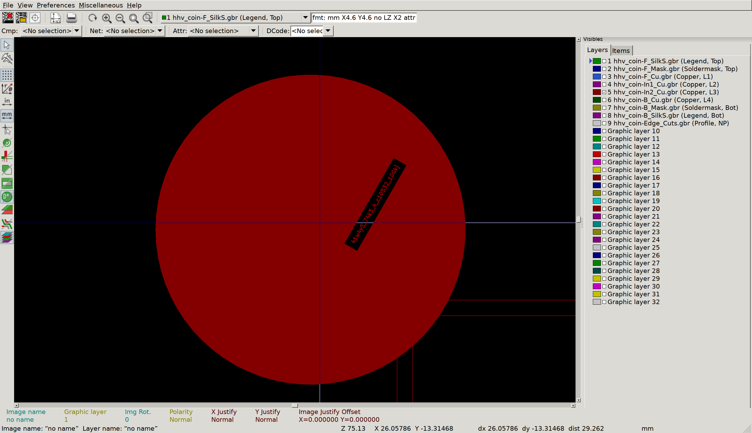
Inner Copper 2
Circuit Cave
This is the way
I’d never seen a .circ file, and wasn’t sure exactly how to open it, so I just took a peek at the start to see what sort of format we were dealing with. Luckily, it comes with a clue!
ross@mjolnir:/h/r/Downloads$ head challenge.circ
<?xml version="1.0" encoding="UTF-8" standalone="no"?>
<project source="2.7.1" version="1.0">
  This file is intended to be loaded by Logisim (http://www.cburch.com/logisim/).

  <lib desc="#Wiring" name="0"/>
  <lib desc="#Gates" name="1"/>
  <lib desc="#Plexers" name="2"/>
  <lib desc="#Arithmetic" name="3"/>
  <lib desc="#Memory" name="4">
    <tool name="ROM">
After installing logisim from apt, we are greeted with a circuit that will shuffle out some obfuscated data on some seven segment displays. Presumably, this data is ascii for our flag. Writing down all the numbers by hand seems burdensome, but if you open the Similation -> Logging window you can add the output of the decoder circuit, and change the radix to 16 to record the hex value every time it changes. Combine this with the log to file option and a method to convert hex as ascii, and you have your flag. Or… close to your flag. It seems that we only actually want every 8th output digit, or whatever is loaded when the Counter(240, 350) signal wraps to zero (when the decimal point is lit).
To speed things up, I recommend changing the Simulate -> Tick Frequency value to something zippier than the default 1Hz.
No, this is the way
I’m a big fan
of verilator! To get the flag here, I made one small addition to
the tick code in the testbench:
  tb->i_clk = 0;
  tb->eval();

  // If the module has flagged the output data is valid, print that
  // character to stdout
  if (tb->o_out) {
    printf("%c", tb->o_data);
  }

  if (tfp) {
    tfp->dump(tickcount * 10 + 5);
    tfp->flush();
  }
The only true way
This stage is similar, but uses nmigen instead of verilog. I’ve seen some nmigen stuff before, but haven’t stuck much of a toe in since I feel I need to thoroughly understand Verilog first. I couldn’t immediately spot a simple way to log data during the similation, so I did this the dumb way - opened up the trace in gtkwave and manually transcribed the data. Sometimes simple works!
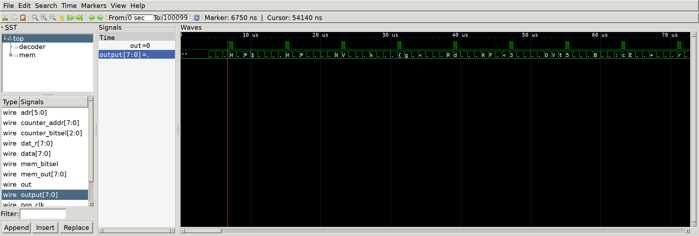
GTKwave to the rescue
Biggest problem I had here was getting nmigen to run properly - there seemed to be some sort of dependency ordering issue, where if I installed nmigen and then nmigen_soc, it would downgrade nmigen to a version that doesn’t have similation. Installing nmigen_soc, then reinstalling nmigen again seemed to fix the problem for my virualenv.
Serial Swamp
Debuggin Interface
Looks like UART at first glance. Add a decoder with a nice default 9600 baud and we see a cute dinosaur in our console output:
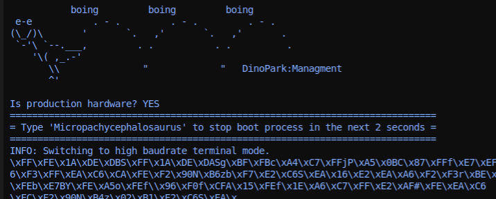
Micropachycephalosaurus
Near the end we see a note that we are switching to fast uart to continue. Add a second decoder with the mildly zippier 115200 baudrate and we can see the rest of our boot prompt, including flag:
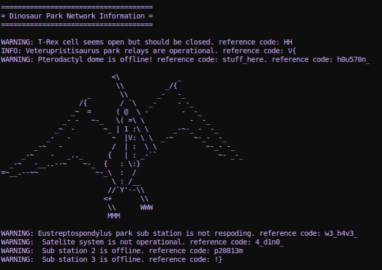
Pterodactyl dome
Lost Record
Wasn’t sure immediately what to make of this one, but googling our signal names (BCK, LRCLK, DOUT) suggests that this is an i2s (audio) interface with 2 channels. Counting our clock cycles, it looks like we have 32 bits per sample, and scanning through some of our early data samples it seems likely that the values are signed, encoded as 2’s complement (instead of toggling between min and max amplitude very quickly).
First step here is to reconstruct the audio, so let’s add an i2s analyzer in Logic and export the data as a CSV. We can then use python to scarf the data and emit a flat binary file with packed sample data, like so:
import csv
import sys
import struct

class Sample(object):
    def __init__(self, time, channel, data):
        self.time = time
        self.channel = channel
        self.data = data

# Read the CSV data
samples = []
with open(sys.argv[1]) as f:
    reader = csv.reader(f)
    reader.next()  # Skip header
    for row in reader:
        try:
            samples.append(Sample(
                float(row[2]), # Timestamp
                int(row[5]),   # Channel (L/R)
                int(row[6])    # Sample data
            ))
        except Exception, e:
            print e
            print row

# Calculate sample rate
time_start = samples[0].time
time_end = samples[-1].time
sample_time = time_end - time_start
sample_count = len(samples)
samples_per_sec = sample_count / sample_time / 2
print "Sample rate: %f" % samples_per_sec

# Create an array of data for each channel
ch0 = []
ch1 = []
for sample in samples:
    if sample.channel == 0:
        ch0.append(sample.data)
    if sample.channel == 1:
        ch1.append(sample.data)

# Interleave the data and pack down into a file
with open('out.stereo.bin', 'wb') as f:
    for pair in zip(ch0, ch1):
        f.write(struct.pack('ii', pair[0], pair[1]))
We can test that the audio sounds right by playing it raw:
aplay -f S32_LE -c 2 -r 44100 out.stereo.bin
My god! They’re coming back! But that doesn’t seem to be the trick. Let’s load this audio into audacity so that we can poke around a bit -
File -> Import -> Raw Data, Signed32LE, 2 channels, 44100 Hz
A fun steganographic technique with audio files is embedding pictures in the Spectrogram of the track. Let’s enable spectrogram view and zoom on in to that final segment:
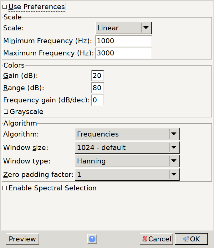
Suggested settings for spectrogram view
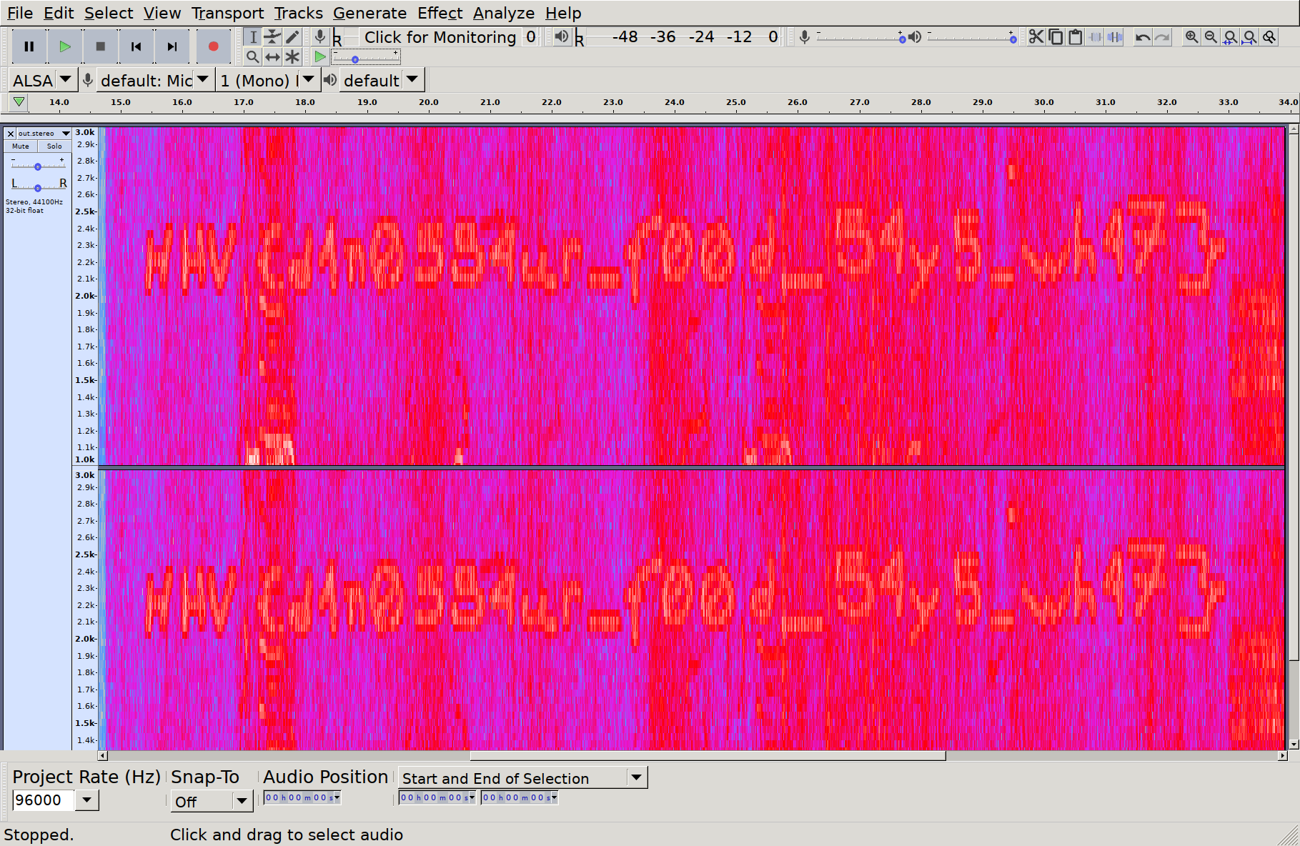
Who drew this here
Lab Control
This one took some doing, mostly due to the sheer size of the datasheet for this chip, and the lack of a clear transaction process overview. But, first things first, we need to make sense of this data - scanning the trace in Logic, it looks like some bog standard SPI transactions. From the chip datasheet, it looks like spi transactions consist of an address and Read/~Write bit, followed by the read/written data. So, let’s decode the data in Logic and export a CSV we can run through some analysis. The output of our export will look like the following:
name,type,start_time,duration,"mosi","miso"
"SPI","enable",3.64e-06,4e-08,,
"SPI","result",6.4e-06,7.52e-06,0x88,0x00
"SPI","result",1.54e-05,7.52e-06,0x00,0x45
"SPI","disable",2.304e-05,4e-08,,
"SPI","enable",3.516e-05,4e-08,,
"SPI","result",3.792e-05,7.52e-06,0x88,0x00
"SPI","result",4.692e-05,7.52e-06,0x00,0x45
"SPI","disable",5.452e-05,4e-08,,
"SPI","enable",6.624e-05,4e-08,,
First things first is to load this data into a programming language where we can mess around a bit, so here’s a quick and dirty loader in C++:
// A 'transaction' begins when ~CS goes low, ends when it goes high.
// Multiple bytes could be transferred per transaction.
struct Txn {
  std::vector<uint8_t> mosi;
  std::vector<uint8_t> miso;
};

// ...

// Load input file
const char *filename = argv[1];
std::fstream fstream_in;
fstream_in.open(filename, std::ios::in);
if (!fstream_in.is_open()) {
  fprintf(stderr, "Failed to open %s\n", filename);
  return -1;
}

// Split each line, and extract our important fields
std::string line;
std::vector<Txn> txns;
bool is_in_txn = false;
Txn active_txn;
while (std::getline(fstream_in, line)) {
  std::stringstream row_ss(line);
  std::string field;
  std::vector<std::string> fields;
  while (std::getline(row_ss, field, ',')) {
    fields.emplace_back(field);
  }
  if (fields[1] == "\"enable\"") {
    is_in_txn = true;
  } else if (fields[1] == "\"result\"") {
    active_txn.mosi.emplace_back(strtoll(fields[4].c_str(), nullptr, 16));
    active_txn.miso.emplace_back(strtoll(fields[5].c_str(), nullptr, 16));
  } else if (fields[1] == "\"disable\"") {
    txns.emplace_back(active_txn);
    active_txn = {};
  } else {
    fprintf(stderr, "Unknown op '%s'\n", fields[1].c_str());
  }
}
Once we have all the transactions, each of which starts with an address, we can
scan through for addresses that are ‘interesting’. First one that looks
promising to me is FIFODataReg - if there’s data, it’s going to be passing
through there. So what happens if we print all the contiguous reads/writes to
that register?
bool last_was_fifo_read = false;
for (auto &txn : txns) {
  // MSB controls read/write
  const bool is_read = txn.mosi[0] & (1 << 7);
  // Address is left shifted one bit just to trip you up
  const uint8_t addr = (txn.mosi[0] & 0x7F) >> 1;

  // Contiguous read from FIFO?
  if (is_read && addr == 0x09) {
    if (!last_was_fifo_read) {
      printf("\n[RD] ");
    }
    printf("%02x", txn.miso[1]);
    last_was_fifo_read = true;
  } else {
    if (last_was_fifo_read) {
      printf("\n");
    }
    last_was_fifo_read = false;
  }

  // Contiguous write to FIFO?
  // [...]
If we run this, we see some interesting long strings of hex data:
[WR] 9320
[WR] 26
[RD] 0400
[WR] 9320
[RD] 8634cd1f60
[WR] 93708634cd1f60
[WR] 93708634cd1f60f5d6
[RD] 08b6dd
[WR] 6008f02d53fda4a78634cd1f
[WR] 3008
[WR] 30084a24
[RD] 6178656c5f3532ffffffffffffffffff
[WR] 6016c47650e887a08634cd1f
[WR] 3016
[WR] 3016b5dd
[RD] 456c65637461646f6e6c6f67697374ff
[WR] 6022f22ed77f55768634cd1f
[WR] 3022
[WR] 302212aa
[RD] 6868765f6c616273ffffffffffffffff
[WR] 26
To get a bit more context, let’s also print some of the other registers that are accessed:
std::unordered_map<uint8_t, std::string> reg_names;
reg_names[0x00] = "Reserved";
reg_names[0x01] = "CommandReg";
reg_names[0x02] = "ComlEnReg";
reg_names[0x03] = "DivlEnReg";
reg_names[0x04] = "ComIrqReg";
reg_names[0x05] = "DivIrqReg";
reg_names[0x06] = "ErrorReg";
reg_names[0x07] = "Status1Reg";
reg_names[0x08] = "Status2Reg";
reg_names[0x09] = "FIFODataReg";
reg_names[0x0a] = "FIFOLevelReg";
reg_names[0x0b] = "WaterLevelReg";

for (auto &txn : txns) { // Same loop as prev prints

  std::string reg_name = std::to_string(addr);
  if (reg_names.find(addr) != reg_names.end()) {
    reg_name = reg_names[addr];
  }
  const uint8_t datum = is_read? txn.miso[1] : txn.mosi[1];
  fprintf(stderr, "%s to %s: %02x", is_read ? "READ" : "WRITE", reg_name.c_str(), datum);
}
If we re-run, we now have some control register writes happening right after our fifo transaction:
[WR] 6022f22ed77f55768634cd1f
WRITE to CommandReg: 0e
Now we’re getting somewhere - right after we write all this data to the FIFO, we’re doing something with a CommandReg. What does 0x0e correspond to?
    if (!is_read && addr == 0x01) {
      switch (txn.mosi[1]) {
      case 0: printf("Command: Idle\n"); break;
      case 3: printf("Command: CalcCRC\n"); break;
      case 4: printf("Command: Transmit\n"); break;
      case 8: printf("Command: Receive\n"); break;
      case 12: printf("Command: Transceive\n"); break;
      case 14: printf("Command: MFAuthent\n"); break;
      }
    }
[WR] 6008f02d53fda4a78634cd1f
Command: MFAuthent
MFAuthent - if we search the datasheet for this, we get a hit well over a hundred pages in:
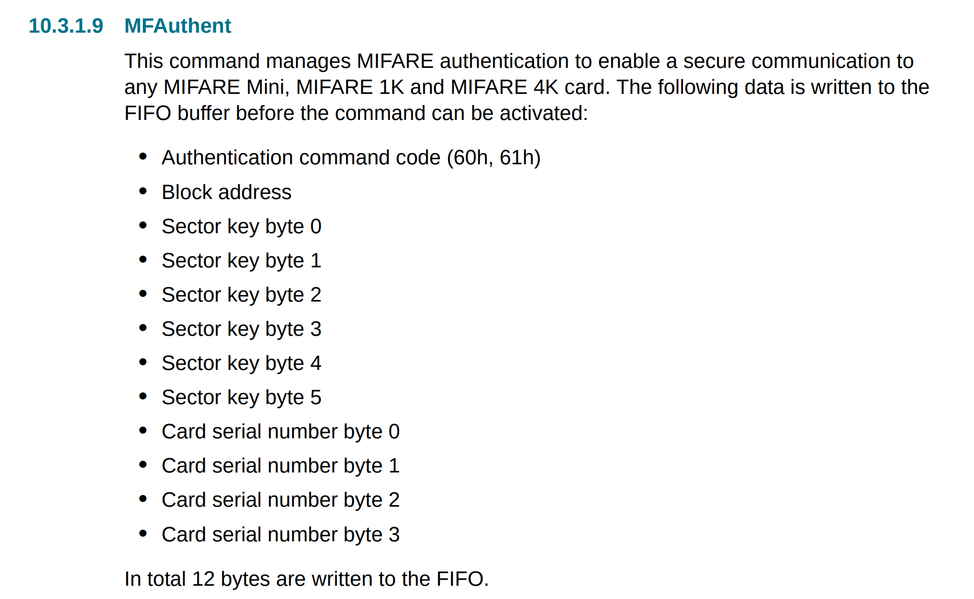
MFAuthent packet structure
If we break down the data written to the FIFO right before this command, it looks like it matches nicely:
60              # Authentication command
08              # Block address
f02d53fda4a7    # Sector key
8634cd1f        # Card serial number (Uid)
If we combine the data from this write (UID and sector key) with the data from
the Transceive calls that happen right after it, we have all the data we need
for our key:
[WR] 30084a24
Command: Transceive

[RD] 6178656c5f3532ffffffffffffffffff
Command: Idle
Broken Display
This is a fun one. We have a trace with a clock, MOSI, reset and ‘DC’ line, and know that we are talking to a display controller. These controllers tend to have Data vs Control modes, so this is likely what our DC signal represents. In order to attack this, we will want to export the commands sent to the LCD, and then run them through a little simulator to recreate the pixel state that the display would have. First step is to get the data out of Logic and into something more parsable. To do this, I added two SPI decoders - both use CLK, MOSI and DC as the serial clock / data / chip select lines, but one of them has CS set as active low and the other has it active high. This way, one will only trigger for data mode transfers and the other only triggers for control mode transfers. If we name these decoders nicely and export, we get data like so:
ross@mjolnir:/h/ross$ head display.csv
name,type,start_time,duration,"mosi","miso"
"data","enable",1.53407174,2.00000002e-08,,
"data","result",1.53408014,3.82e-06,0x5A,0x00
"data","result",1.53408418,3.82e-06,0x69,0x00
"data","result",1.53408974,3.8e-06,0x02,0x00
"data","result",1.53409378,3.8e-06,0x01,0x00
"commands","enable",1.53412622,1.99999999e-08,,
"data","disable",1.53412622,1.99999999e-08,,
"commands","result",1.53413476,3.82e-06,0xB2,0x00
"commands","disable",1.53416404,1.99999997e-08,,
with a little shell magic, we can preprocess this a little to make our lives easier later:
ross@mjolnir:/h/ross$ cat display.csv | grep result | cut -d , -f 1,5 > data_cmd.csv
ross@mjolnir:/h/ross$ head data_cmd.csv
"command",0x28
"command",0xDF
"data",0x5A
"data",0x69
"data",0x02
"data",0x01
"commands",0xB2
"data",0x0C
"data",0x0C
"data",0x00
Now, let’s load this up and see what’s involved in replaying this data. First, some boilerplate:
struct Packet {
  enum Type {
    COMMAND,
    DATA,
  };
  Type type;
  uint8_t data;
};

// [...]

// Parse file
const char *filename = argv[1];
std::fstream fstream_in;
fstream_in.open(filename, std::ios::in);
if (!fstream_in.is_open()) {
  fprintf(stderr, "Failed to open %s\n", filename);
  return -1;
}
std::string line;
std::deque<Packet> packets;
while (std::getline(fstream_in, line)) {
  std::string::size_type comma_pos = line.find(",");
  std::string type = line.substr(0, comma_pos);
  std::string value_str = line.substr(comma_pos + 1);
  Packet p;
  p.type = type == "\"data\"" ? Packet::Type::DATA : Packet::Type::COMMAND;
  p.data = strtol(value_str.c_str(), nullptr, 16);
  packets.emplace_back(p);
}
We now have a queue of command and data packets. From here, we just need to
peel off the first command, see how many data bytes we need to associate with
it, update the state of our fake LCD, and rinse and repeat. In fact, it turns
out we can ignore most of the setup commands, though it’s useful to note that
the LCD is programmed in 16-bit data mode, where each pixel is RGB565. Skipping
through the rest of the commands from the datasheet, we come across three that
we definitely want to implement - the Row/Column window select, and the RAMWR
commands. The LCD controller in question does not allow you to addresss the
entire memory space at once, instead you have to define an X region xs (x
start) to xe (x end), and similarly a Y region, into which the RAMWR function
will write. So, let’s do some accounting for these in a little loop:
// Cannot understand why STL containers don't include a method for this
auto next_packet = [&]() -> Packet {
  auto p = packets.front();
  packets.pop_front();
  return p;
};

// Row/column window, and current pixel write address
uint16_t xs = 0, xe = 0xef;
uint16_t ys = 0, ye = 0x13f;
uint16_t x_addr = xs;
uint16_t y_addr = ys;

// State machine
while (packets.size()) {
  // Take first packet
  auto packet = next_packet();

  // Ignore unexpected data packets
  if (packet.type == Packet::Type::DATA) {
    fprintf(stderr, "Unexpected data packet %02x\n", packet.data);
    continue;
  }

  // Switch next packet command
  switch (Command(packet.data)) {

  case Command::COL_ADDR_SET: {
    // Consume 4 data packets
    auto xs15_8 = next_packet();
    auto xs7_0 = next_packet();
    auto xe15_8 = next_packet();
    auto xe7_0 = next_packet();
    xs = xs15_8.data << 8 | xs7_0.data;
    xe = xe15_8.data << 8 | xe7_0.data;
    x_addr = xs;
    fprintf(stderr, "xs: %4d, xe: %4d\n", xs, xe);
  } break;

  case Command::ROW_ADDR_SET: {
    // Consume 4 data packets
    auto ys15_8 = next_packet();
    auto ys7_0 = next_packet();
    auto ye15_8 = next_packet();
    auto ye7_0 = next_packet();
    ys = ys15_8.data << 8 | ys7_0.data;
    ye = ye15_8.data << 8 | ye7_0.data;
    y_addr = ys;
    fprintf(stderr, "ys: %4d, ye: %4d\n", ys, ye);
  } break;

  default: {
    fprintf(stderr, "Unhandled command 0x%02x\n", packet.data);
  } break;
  }
}
Now that we have the row/column data, we need to actually write pixels to those addresses. We create a buffer to hold our pixel data & some helper tools to write data, then handle that command type in our loop like we did the row/col addresses:
// Display is a known size
const int rows = 240;
const int cols = 320;
static uint8_t pixels[rows * cols * 3];
auto write_pixdata = [&](int row, int col, uint16_t data) {
  // input data is rgb 565
  uint8_t r = (data >> 11) & 0b11111;
  uint8_t g = (data >> 5) & 0b111111;
  uint8_t b = (data >> 0) & 0b11111;
  const int offset = (row * cols + col) * 3;
  pixels[offset + 0] = r;
  pixels[offset + 1] = g;
  pixels[offset + 2] = b;
};

// [...]

// Inside our switch statement from above
case Command::RAMWR: {
  // Consume as many data packets as we can
  int wrote = 0;
  while (packets.front().type == Packet::Type::DATA) {
    // Pop 2 data packets
    auto dp0 = next_packet();
    auto dp1 = next_packet();
    uint16_t dat = dp0.data << 8 | dp1.data;
    write_pixdata(x_addr, y_addr, dat);

    // Handle row/column address increment
    x_addr++;
    if (x_addr > xe) {
      x_addr = xs;
      y_addr++;
    }
    if (y_addr > ye) {
      y_addr = ys;
    }
    wrote++;
  }
  fprintf(stderr, "Wrote %d pixels\n", wrote);
} break;
This should be enough to regenerate a pixel buffer, but we need a way to see it. Luckily, openGL makes this relatively straightforward - we can create a texture, load the pixel data into it, then render it as a flat square using the following incantations:
// Glut needs a render functin to call; annoyingly can't use a std::function
// so work around by just making key state static
static int window_w = cols, window_h = rows;
static GLuint gl_texture;
auto gl_display = []() {
  glClear(GL_COLOR_BUFFER_BIT | GL_DEPTH_BUFFER_BIT);

  // Generic 2d orthographic view
  glViewport(0, 0, window_w, window_h);
  glPushMatrix();
  glOrtho(0, window_w, window_h, 0, -1, +1);

  // Render texture as full screen
  glBindTexture(GL_TEXTURE_2D, gl_texture);
  glEnable(GL_TEXTURE_2D);
  glBegin(GL_QUAD_STRIP);
  glTexCoord2f(0.0f, 1.0f);
  glVertex2f(0, window_h);
  glTexCoord2f(0.0f, 0.0f);
  glVertex2f(0, 0);
  glTexCoord2f(1.0f, 1.0f);
  glVertex2f(window_w, window_h);
  glTexCoord2f(1.0f, 0.0f);
  glVertex2f(window_w, 0);
  glEnd();
  glDisable(GL_TEXTURE_2D);
  glBindTexture(GL_TEXTURE_2D, 0);

  glPopMatrix();
  glFlush();
  glutSwapBuffers();
};

auto gl_resize = [](int w, int h) {
  window_w = w;
  window_h = h;
};

// Initialize GLUT
glutInit(&argc, argv);

// Create a window to display in
glutInitDisplayMode(GLUT_RGB | GLUT_DOUBLE | GLUT_DEPTH);
glutInitWindowSize(window_w, window_h);
glutInitWindowPosition(0, 0);
glutCreateWindow("Broken Display");

// Set up our render callbacks
glutIdleFunc(gl_display);
glutDisplayFunc(gl_display);
glutReshapeFunc(gl_resize);

// Generate texture using our pixel data
glGenTextures(1, &gl_texture);
glBindTexture(GL_TEXTURE_2D, gl_texture);
glTexImage2D(GL_TEXTURE_2D, 0, GL_RGB, cols, rows, 0, GL_RGB,
             GL_UNSIGNED_BYTE, pixels);
glTexParameteri(GL_TEXTURE_2D, GL_TEXTURE_MAG_FILTER, GL_LINEAR);
glTexParameteri(GL_TEXTURE_2D, GL_TEXTURE_MIN_FILTER, GL_LINEAR);
glTexParameteri(GL_TEXTURE_2D, GL_TEXTURE_WRAP_S, GL_CLAMP);
glTexParameteri(GL_TEXTURE_2D, GL_TEXTURE_WRAP_T, GL_CLAMP);
glPixelStorei(GL_UNPACK_ROW_LENGTH, 0);
glBindTexture(gl_texture, 0);

glutMainLoop();
With this, we get a cute little QR code in hacker green. My phone had a hard time reading this as-is, so I had to screenshot it, open it in GIMP and value invert the colours to get something it was happier with.