DEFCON 27: Badge Writeup
Sun, Aug 11, 2019 Companion code for this post available on GithubIf you just want to cut to the chase and flash your own badge with the Chameleon firmware, grab this build and jump to the “Flashing the badge” section.
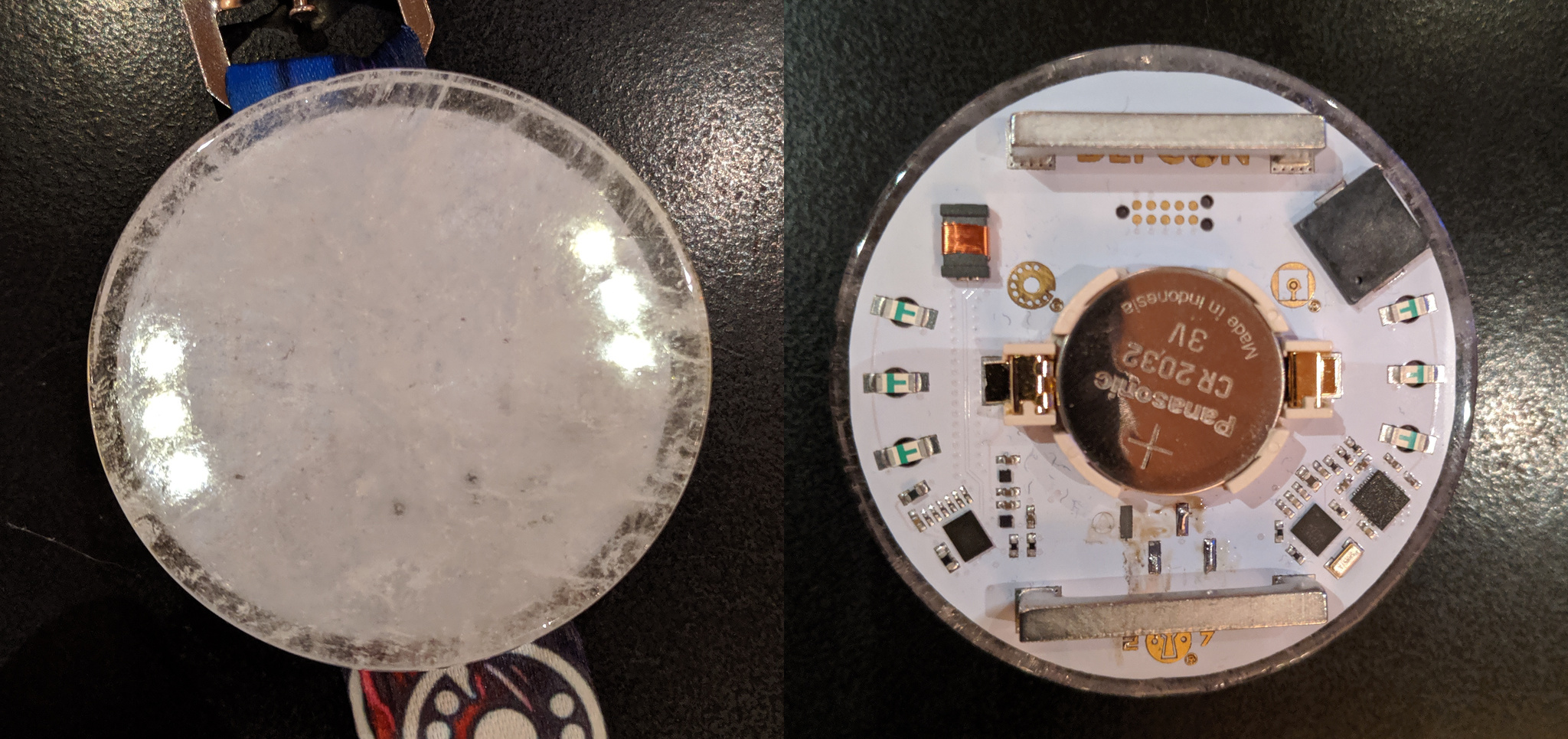
This year at DEFCON, we were lucky enough to be provided with another electronic badge, this time courtesy of Joe Grand. The badge is a very sleek design featuring a quartz face, lanyard mounting straps and a Kinetis KL27 series microcontroller (specifically, a KL27P64M48SF2 ). The badge also has an unusual communication mechanism, an NXH2261UK Near-Field Magnetic Induction chipset and antenna.
This year the core badge hardware was the same across badge types, the only differences being a ‘badge type’ byte in the firmware for each badge, and various colours of quartz on the non-human badges.

Human Badge, Front and Back
Some more information on the badge itself, including pictures of all the badge types, can be found on Joe Grand’s Website.
If one wanted to complete the badge without any trickery, they would need to go around the conference interacting with all of the other badge types, including a select few ‘magic’ badges, in order to complete their badge. If we peek the source code of the badge, we can see exactly what’s needed:
// Bit masks for badge quest flags
#define FLAG_0_MASK 0x01 // Any Valid Communication
#define FLAG_1_MASK 0x02 // Talk/Speaker
#define FLAG_2_MASK 0x04 // Village
#define FLAG_3_MASK 0x08 // Contest & Events
#define FLAG_4_MASK 0x10 // Arts & Entertainment
#define FLAG_5_MASK 0x20 // Parties
#define FLAG_6_MASK 0x40 /* Group Chat (all 6 gemstone colors:
                          Human/Contest/Artist/CFP/Uber +
                          Goon + Speaker + Vendor + Press + Village) */
To save yourself some walking and learn a bit more about the badge firmware, read on and we’ll cover two ways to complete the badge the hardware hacking way.
Prerequisites
In order to debug or flash your device, you’ll need one of the many ARM programmers available. Joe Grand recommended NXP’s own LPC-Link 2 but you can likely use any debug probe like the Segger J-Link ($$), or the Black Magic Probe (much more affordable), which is what I’ll be using.
You will also need a particular TagConnect cable, the TC-2050-IDC-NL-050-ALL, or some fine gauge wire and a steady hand. If you plan on developing many of your own ARM based designs, I would strongly recommend you pick up the cable. The convenience and cost savings of not having to place .127” pin headers quickly makes up for the price of the cable. You may also want to pick up some cable retaining clips, which make extended debugging require one fewer arms.
If you intend to compile for or flash your badge, you will also need the GCC ARM toolchain, which you can install using your package manager of choice:
sudo apt install binutils-arm-none-eabi gcc-arm-none-eabi gdb-arm-none-eabi
First Approach: No firmware rewriting
Our initial goal was to solve the badge “legit” (for some definition of the word), by not rewriting the firmware in any way. For this method, you will need to populate the 1.8V serial headers on the opposite side to the tag-connect pads. This method will require two badges, and the workflow goes like this:
- On badge A, we connect our favourite debugger (GDB) over SWD
- We then overwrite the game state in memory, tricking that badge into thinking it is solved. This is not persistent across reboots (since it’s only a change to SRAM), but will be good enough for now.
- We then un-halt the CPU on badge A, and connect to it over UART.
- On the UART, now that the badge is ‘complete’ we have three extra options - one of which is ‘craft packet’. We can use this to spoof packets from other badge types.
- On badge A, we iterate through broadcasting all badge types (with magic bit set), and after two rounds of this bade B will be complete, as though it had actually interacted with the real badges
- We can now reboot badge A, which reverts to being a normal, zero progress badge.
In order to trick badge A into thinking it’s complete, we first need to figure
our what memory location holds the game state variable. I’m not skilled at RE,
so instead I’ll cheat a little, and use the linker map, which is available on
the
DEFCON media
server.
As a quick recap for those that haven’t seen linker maps before, the map
contains the load and virtual address of all variables and functions in the
finished binary. It can come in extremely helpful when debugging embedded
systems, as we’ll see here. If we search through the map file for the
badge_state variable, we can see that it’s located at SRAM address
0x1ffffcdc:
 .bss.attract_state
                0x1ffffcdb        0x1 ./source/dc27_badge.o
 .bss.badge_state
                0x1ffffcdc        0x1 ./source/dc27_badge.o
 .bss.badge_type
                0x1ffffcdd        0x1 ./source/dc27_badge.o
This means that to trick our badge, we just need to overwrite this one memory address. To do that, we’ll connect to the badge over SWD (check the “Flashing the badge” section below for a more thorough explanation of this process) in order to debug it using GDB. Once you’ve attached to the badge, there’s only one necessary command to set the flags:
set {char}0x1ffffcdc = 7
Once you’ve done that, hit c for continue to un-halt the badge CPU. You can
now connect the four serial lines of the black magic probe to the UART pinout
on the opposite side of the battery. With the badge face down and the SWD
connector to the south, the staggered pinout for serial is GND (black),
TX (green), RX(purple), VCC (red). Unlike with some of the other programmers,
you must connect the power line of the black magic probe in order to power the
on-board level shifter. With other programmers, be aware that they may attempt
to power the badge themselves, and applying voltages over the expected 1.8V
badge voltage may cook your badge.
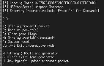
Now that you have your game state updated, when you connect to the serial
console using screen /dev/ttyACM1 115200, you should be greeted with three
additional options:

Extended serial commandset on complete badge
The last of these, ‘Update Transmit Packet’, is what we’ll be using to get our B badge to complete. If we take a look at the firmware, we can see how the packets are constructed:
struct packet_of_infamy // data packet for NFMI transfer
{
  uint32_t uid;   // unique ID
  uint8_t type;   // badge type
  uint8_t magic;  // magic token (1 = enabled)
  uint8_t flags;  // game flags (packed, MSB unused)
  uint8_t unused; // unused
};
With this info, we can craft our own packets, masquerading as any badge we want. Here’s a complete list of badge types, and the command you need to send in order to become them:
Human   U 772502840001ff00
Goon    U 772502840101ff00
Speaker U 772502840201ff00
Vendor  U 772502840301ff00
Press   U 772502840401ff00
Village U 772502840501ff00
Contest U 772502840601ff00
Artist  U 772502840701ff00
CFP     U 772502840800ff00
Uber    U 772502840901ff00
After manually cycling through these on badge A to unlock badge B, you can then reset badge A and do the same for it, resulting in two ‘legitimately’ unlocked badges. Of course, if that’s not enough for you, we can take it one step further: automating the process by building a Chameleon badge.
Second Approach: Building a Chameleon
After spending several hours manually rotating packets to advance other badges, we decided it was time to automate the process. Since the firmware is freely available on the DEFCON Media Server we can grab it, modify it to our heart’s content and then flash it to our badge. The first stumbling block I hit is that the software is written to rely on NXP’s own libc implementation, Redlib, and downloading the official NXP toolchain on the DEFCON wifi was going to take 8 hours. Instead of that, I rewrote the software slightly to use Newlib, which is packaged along with the GCC ARM toolchain. The full modified firmware building against newlib-nano (and including the chameleon patches) is available in this Github repo.
Once we have the original firmware building, we can go about editing it to broadcast as every other badge type. In order to hook this in, there are two main changes to be made. The first is that we need some way of keeping track of time - the systick implementaion Joe used here only acts as a blocking countdown timer, since he’d just been using it for delays. Since we want to keep an idea of how long we’ve been broadcasting as one badge, we need to add a second counter we can use as monotonic time. This is a quick two line change:
--- a/source/dc27_badge.c
+++ b/source/dc27_badge.c
@@ -423,6 +423,7 @@ static uint32_t pflashSectorSize = 0;

 // Timer
 volatile uint32_t g_systickCounter;
+// Monotonic count-up timer
+volatile uint32_t g_monotonicTime = 0;
 volatile bool g_lptmrFlag;

 // UART2 (to/from host)
@@ -2935,6 +2952,7 @@ void SysTick_Handler(void)
     {
         g_systickCounter--;
     }
+    g_monotonicTime++;
 }
Now, every time the SysTick interrupt is generated, as well as decrementing the
delay timer we will also increment our own monotonic timer.
The SysTick timer is configured to interrupt every 1ms, however it is also
paused when the badge enters sleep mode, which it does while not actively
transmitting / receiving packets. Since our timer will only advance during
transmit, we can use a relatively short interval in our code, since it will get
stretched out as the chipset sleeps. With the timer in place, the patch for a
‘chameleon’ badge is relatively straightforward, and is added at the top of the
while (1) block in main():
// Outside our loop, declare our state variables:
static uint32_t state_change_timer = 0;
// Inside our while(1) loop, handle the chameleon code
if (g_monotonicTime > state_change_timer + 1000) {
  // If it's been 1000 systicks since we last changed our badge state, it's
  // time to update. First, reset our timer to the current monotonicTime.
  state_change_timer = g_monotonicTime;
  // Now, increment our badge type by 1, changing our identity.
  nxhTxPacket.type = nxhTxPacket.type + 1;
  // If we've cycled through all the way to UBER (which is currently read only
  // as Human, and so not particularly useful to broadcast) then go back to the
  // beginning, skipping human and starting at Goon.
  if (nxhTxPacket.type >= UBER) {
    nxhTxPacket.type = GOON;
  }
  // Having changed our packet struct, we now need to load it into the
  // NXH2261 to be broadcast.
  if (KL_UpdatePacket_NXH2261(nxhTxPacket)) {
    // If we fail once, try again. Joe seems to do this elsewhere in the code.
    if (KL_UpdatePacket_NXH2261(nxhTxPacket)) {
      // If we fail a second time, give up and log a message.
      PRINTF(msg_nfmi_packet_err);
    }
  }
}
There are some other fun things you can do in the firmware, such as enabling a
longer version of
everyone’s favourite song,
or editing your LED pattern, but for the
purposes of this post those are left as exercise to the reader. Once you’ve
made your mods, from the Firmware/Debug folder you can run
make dc27_badge.axf to rebuild the firmware. If all goes well, you should get
a nice printout of your memory utilization and a success message:
Memory region         Used Size  Region Size  %age Used
   PROGRAM_FLASH:       58224 B        64 KB     88.84%
            SRAM:        5228 B        16 KB     31.91%
         USB_RAM:          0 GB        512 B      0.00%
Finished building target: dc27_badge.axf
Flashing the badge
Now that we have our updated badge firmware, it’s time to flash. I’ll assume
a black magic probe here, for other probes please consult their manuals.
The first thing we need to do is update the firmware on our black magic probe.
There seems to be a bug in the latest official firmware (at time of writing,
1.6.1) where the KL27x64 series is not recognized properly, and will show up as
a generic Cortex-M part. This causes the flashing to fail, since the KL27x64
require a specific flash unlock code before programming.
To update your black magic probe, clone the firmware repo from
Github
build it with make and then perform a DFU update on your probe with the
following command:
sudo dfu-util -d 1d50:6018,:6017 -s 0x08002000:leave -D src/blackmagic.bin
Now that the firmware is updated, we can connect to the badge. You will first need to either
- Remove the quartz face of your badge (gently) with a shim
- Cut down the length of your tagconnect locating pins so that they are ~0.5mm shorter than the pogo pins
Removing the quartz will keep your cable intact, and allow you to clip the cable in place for longer development sessions. The adhesive is strong enough that it can survive being carefully removed and reattached a few times.
Once you have connected the tag-connect cable to the badge one way or the
other, it is time to fire up arm-none-eabi-gdb and do our dirty work. Once
you have GDB open, we first need to point it to the black magic probe as our
remote debugging tool. To do this, we use the command
target extended-remote /dev/ttyACM0, where /dev/ttyACM0 should be the first
of the two serial endpoints exposed by the black magic probe.
Now that we have GDB connected to the probe, we can scan for devices, using
monitor swdp scan. This should return a list of two devices for the DEFCON
badge: the chipset, and a recovery mode that I have not explored.
N.B: If your scan doesn’t return KL27x64 M0+, and instead returns ‘Generic
Cortex-M’, close GDB and retry. This seems to be a race condition of some
sort.
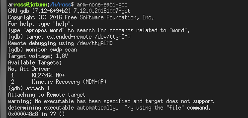
Since we want to debug the main chip, we attach to it using attach 1, which
halts the core and prints our current stack frame. A successful attach
session should look somewhat like the following:

Successful attach over GDB
Now that we are hooked up and ready to go, flashing the badge is relatively
straightforward: we need to select the file to load using
file /path/to/dc27_badge.axf, and then to program the badge we just need to
run load. If you don’t want to compile your own firmware, you can use
this build
of a chameleon badge that I’ve created.
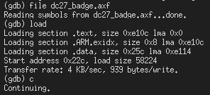
Once you run load, you should see output like the following:

Firmware flashing over GDB
Once the load is complete, your badge will still be in a halt state. To get it
running, either hit c for continue in GDB, or detach the probe and power
cycle the badge. You should now have your own chameleon or otherwise custom
firmware loaded up!
Wrapup
If this all seemed interesting, don’t be afraid to try it! For some more reading on developing for embedded ARM systems you can check out this tutorial series, and to keep abreast of the progress hacking next year’s badge, join the Hack the Badge slack for discussion.
You can also check out some other writeups of the badge, by some of the great people I met at the HHV this year: