Clocking In
Wed, Jun 28, 2017 Companion code for this post available on GithubSome time ago now, I built my first moderately complex electronics project, an ethernet connected Nixie clock that pulled the time over NTP (all the code and schematics for which are on Github for those interested). Sadly, the one that had been running continuously since then croaked in a non-obvious enough way that I couldn’t repair it. Rather than re-fabricate the old design, I took this as an opportunity to revise the design and make some modifications.
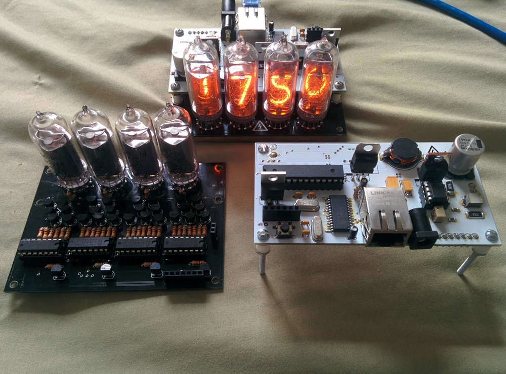
The original two-part design, witn IN-16 tubes
While the previous version did have NTP, it was over ethernet (the ENC28J60 is considerably cheaper than any wifi chipset, especially at the time) which limited the locations that the clock could be plugged in. Version one was also a four digit display, which was nice and compact but doesn’t have the engagement of a noticeably ticking seconds place. Since adding a seconds place would make the design quite wide, I opted for more of a desk-placard form factor than the relatively cubelike design of v1. For style, the front would be just the display. Since the IN-16 tubes used for the first version are uprights, for this design I switched over to IN-12 tubes, which have their display in the same plane as the PCB they are mounted to.
So the first step was to make the smallest possible board that can hold the display tubes themselves, and use this as a reference for all the other boards:
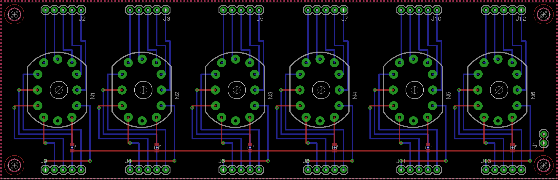
This gives us a roughly 6.25” x 2” area to be getting on with, so next is to make sure that the brains of the operation can all fit into that space. The main things we need to cram in are:
The MCU: This will need to wrangle the WiFi chipset to fetch NTP offsets from the net, as well as marshal that data in such a way as to drive the display logic. Since there’s not too much processing going on here, we don’t need a hugely beefy chip. Here I’ll be using the Atmel ATMEGA238P, since it’s more than capable for the task and allows me to take advantage of the Arduino software ecosystem. This MCU doesn’t require much by way of supporting components - just a crystal.
Wifi: I know that the ESP8266 is the darling these days, but I could never get one to program correctly and have a (perhaps irrational) preference for SPI over UART. To that end, my go-to wifi chip is the Atmel ATWINC1500, which is somewhat more expensive but has proved easier to work with. It does run at 3.3V though, unlike the ATMEGA which will be running off 5V.
Boost Converter: In order to drive the Nixie tubes, we’ll need around a 170V potential on the anode. For step-up designs like this I usually use the MAX1771 controller, which tends to work well for high voltage boost circuits. I ran intp an issue with the previous design where there was a barely audible ringing, which I think was due to small traces on the boost circuit. This time I resolved to use much larger fills for the high current path on the boost circuit to try and eliminate that issue.
At the end of the day, the control board is split into three broad nets - the 12V input from the barrel jack on the back feeds the boost circuit on the right of the PCB, as well as feeding the 5V logic through an ordinary linear regulator. Since the current draw on the MCU isn’t significant, the regulator doesn’t seem to get too hot. The 5V logic is then linked to the WiFi module through some level shifters, and the power is fed through a second regulator.
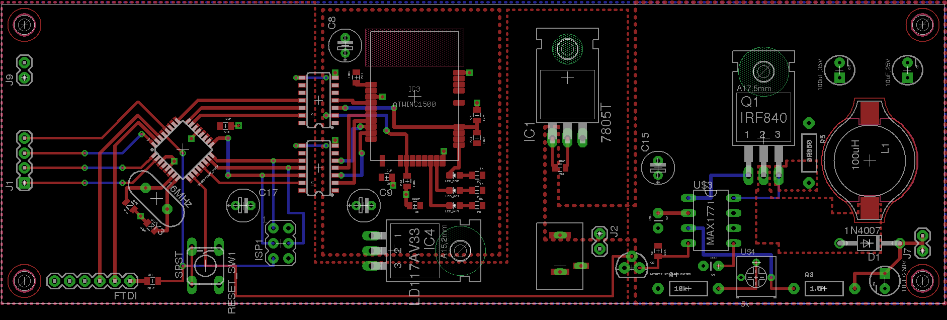
Final layout of the control board, with room to spare
The middle board is fairly boring - in order to drive the nixies, the active number needs the cathode pulled low to allow current to flow. In order to handle any possible high potential on the cathode lines, each one is connected to ground through a high voltage MPSA42 transistor, with a collector-emitter voltage of 300V (more than enough for the 170V that it could be required to handle in this circuit). Since the MCU can’t drive all 45 cathode pins itself, I’ll be using ordinary LS595 shift registers to translate serial data from the MCU into parallel output to all the cathode driving transistors. If we wanted a design that could possibly be used for other numeric display functions we’d wire up all of the digits on the nixie tubes, but since that would add significantly more connections (and so more 595 chips (and so more complexity)) I’ve opted not to here.
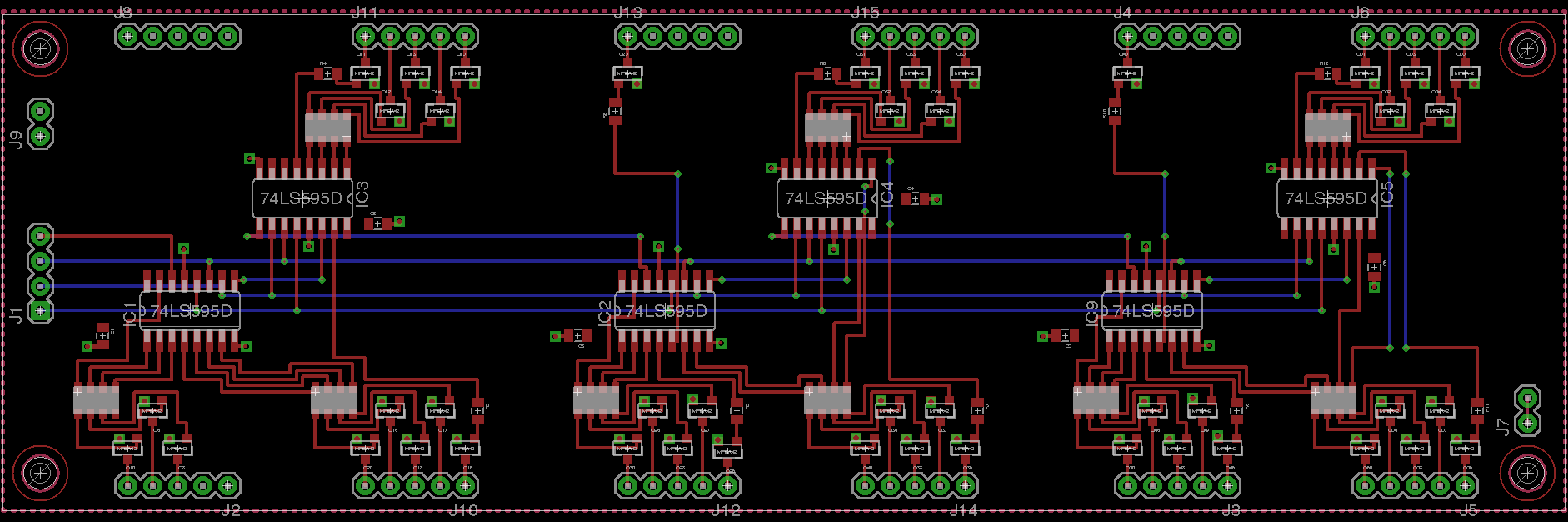
The shift register mux board
Now that all of the hardware is together, the only thing left is to program the thing. The full code is available here, if you want to have a read through the entire thing, but the gist is thus:
- On boot, and every hour thereafter, ask the NTP server for the current time
- Transform the time to local time, and store the difference between the current local time and the current internal monotonic clock.
- Every 50 milliseconds, calculate the current local time based on the millisecond offset from the NTP server and convert it into a series of bytes to be written to the shift register
The most interesting part to write was the NTP code - I’ve never gone in depth on the NTP spec before, and like many RFCs it’s an interesting read. Version 4, which we’ll use here, is defined in RFC #5905. Under section 7.3, in figure 8, we can see a nice diagram of the packet header format. This is all we need to be able to get the time from the net, as demonstrated here:
/**
 * Issue an NTP sync request to our timeserver.
 * This involves building up a packet by hand - reference to RFC5905 is key
 * https://tools.ietf.org/html/rfc5905#section-7.3
 */
unsigned long sendNTPpacket(IPAddress& address) {
    // Zero out our packet buffer
    memset(packetBuffer, 0, NTP_PACKET_SIZE);

    // Our first byte contains the Leap Indicator, Version Number and Mode.
    packetBuffer[0] = (
        // Leap indicator is set to 3 (clock not sync'd)
        0x03 << 6 |
        // Version number is 4, the current version of NTP
        0x04 << 3 |
        // Our mode is 3, client
        0x03 << 0
    );

    // Next is stratum, in this case unspecified
    packetBuffer[1] = 0x00;

    // Polling interval - the maximum interval between successive messages.
    // This is a funky variable; it's in log2 seconds.
    // 6 is the recommended lower bound, so we'll use that
    packetBuffer[2] = 0x06;

    // The precision of our own clock.
    // This is also in log2 seconds (signed). So to specify microseconds, that's
    // 1 / 1,000,000 seconds. log_2(1000000) is 20 (well, 19,9), so for one
    // onemillionth of a second we want -20.
    packetBuffer[3] = 0xEC;

    // 8 bytes intentionally left blank for the root delay and root dispersion.
    // These count time lags for the reference clock, and we don't really care.

    // Next 32 bits are the Reference ID. I can't quite determine what exactly
    // the spec wants here, but 'INIT' is a valid kiss code for not having
    // synchronized yet so we'll go with that
    packetBuffer[12]  = 'I';
    packetBuffer[13]  = 'N';
    packetBuffer[14]  = 'I';
    packetBuffer[15]  = 'T';

    // There are more fields in an NTP packet, but we don't care about them here
    // Now that the packet is all set, we can send it off to the timeserver
    // NTP runs on port 123
    Udp.beginPacket(address, 123);
    Udp.write(packetBuffer, NTP_PACKET_SIZE);
    Udp.endPacket();
}
Once we’ve sent off that request, we hope that we’ll get a response back, and can deal with it pretty easily:
/**
 * Parse the response datagram from the NTP timeserver
 */
void parseNtpResponse() {
    // Read the response packet into the buffer
    Udp.read(packetBuffer, NTP_PACKET_SIZE);

    // The info we care about, the NTP timestamp, begins at byte 40 in the
    // packet and is 4 bytes long. Grab those bytes and convert them to an
    // unsigned long.
    unsigned long highWord = word(packetBuffer[40], packetBuffer[41]);
    unsigned long lowWord = word(packetBuffer[42], packetBuffer[43]);

    // NTP counts seconds since 1900, not seconds since 1970.
    unsigned long secsSince1900 = highWord << 16 | lowWord;

    // So to convert to UNIX epoch, just need to subtract 70 years in seconds
    const unsigned long seventyYears = 2208988800UL;
    unsigned long epoch = secsSince1900 - seventyYears;

    // Now, convert that epoch to our local timezone
    unsigned long localTime =  usEastern.toLocal(epoch);

    // And update our millisecond offset
    updateOffset(localTime);
}
Finally, we have our update code. It’s pretty basic - switching on each of
the digits allows us to easily control each bit output, but seems verbose. It
may be possible to get a better density using some refined bit twiddling, but
the explicit form is easy to modify, and handles the fact that our outputs are
somewhat willy-nilly.
/**
 * Takes the hours, minutes and seconds and maps them into bits on the shift
 * registers. Elegant? Perhaps not. Functional? Yes.
 */
void write595Time(uint8_t hours, uint8_t minutes, uint8_t seconds) {

    // Create an output buffer
    uint8_t out[] = { 0, 0, 0, 0, 0, 0 };

    // Low 3 bites on the first shift register control the hours tens
    switch (hours / 10) {
        case 0: out[0] |= (1 << 0); break;
        case 1: out[0] |= (1 << 1); break;
        case 2: out[0] |= (1 << 2); break;
    }

    // The upper bits of the first, and lower of the second, registers control
    // hours ones
    switch (hours % 10) {
        [...]
    }

    [...]

    // Now shift out the data to the registers
    digitalWrite(N_RCK, LOW);
    for (int i = 5; i >= 0; i--) {
        shiftOut(N_SER, N_SCK, MSBFIRST, out[i]);
    }
    digitalWrite(N_RCK, HIGH);
}
The easily editable switch tables allowed for some last minute tweaking of values, after I realized that some of my between-board tracings had been pin-shifted slightly
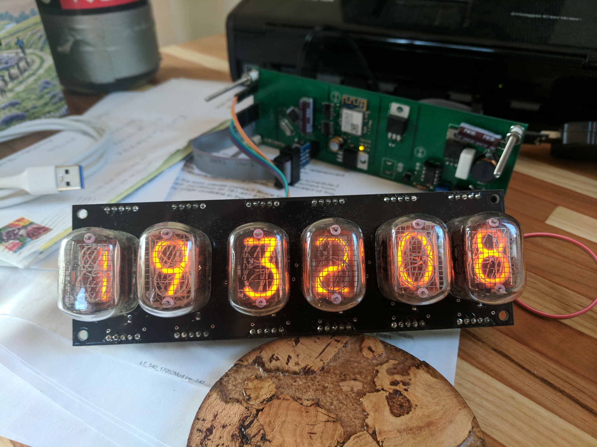
Testing the output mapping
With the code loaded, I once again have a functioning timepiece on my desk. At some point I’ll fabricate some sort of housing, but until then the bare board aesthetic will have to do.
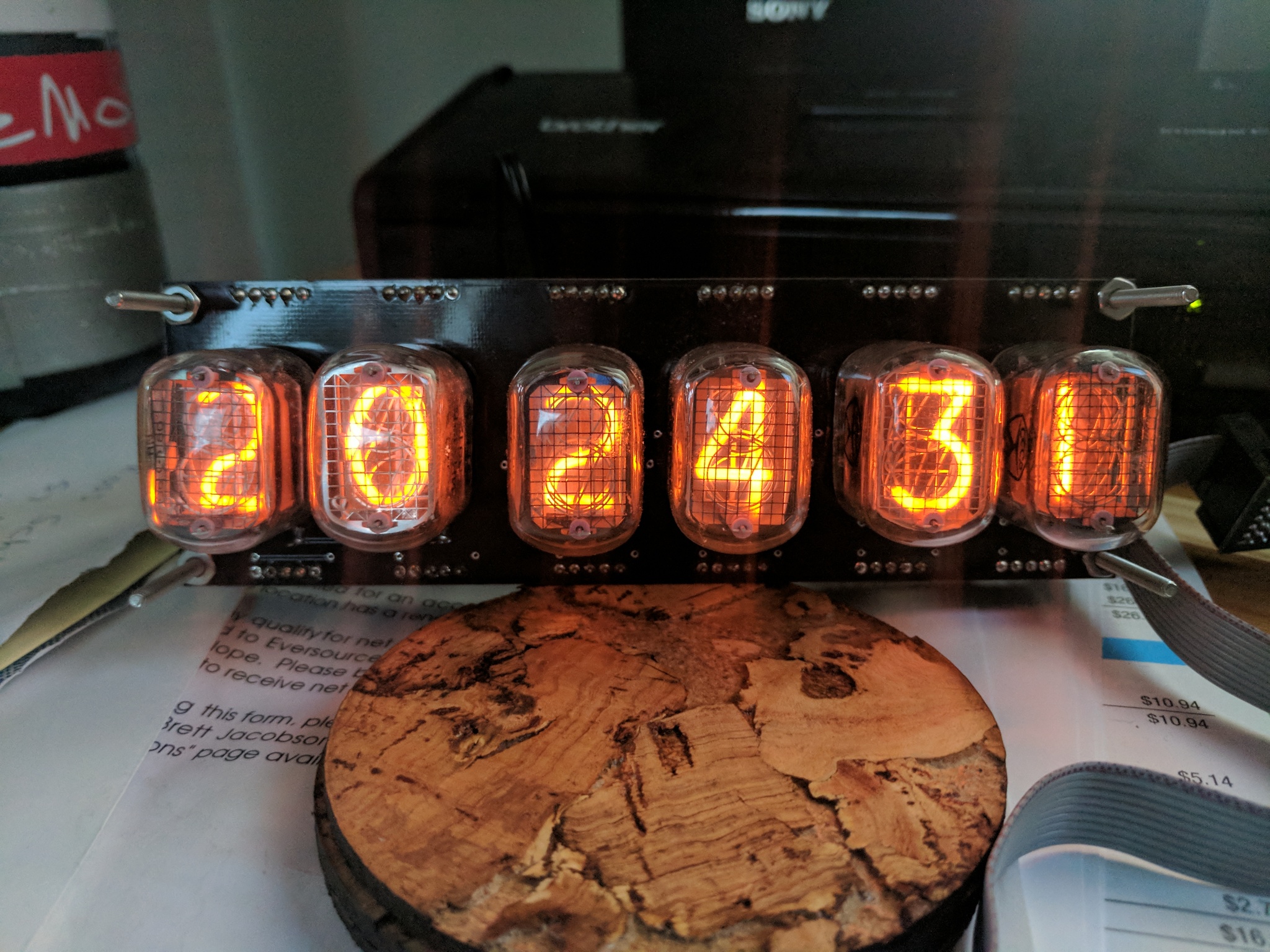
The assembled version two
Bonus GIF
All of the EAGLE design files for the clock, as well as the code for the atmega, are available in this Github repo.